

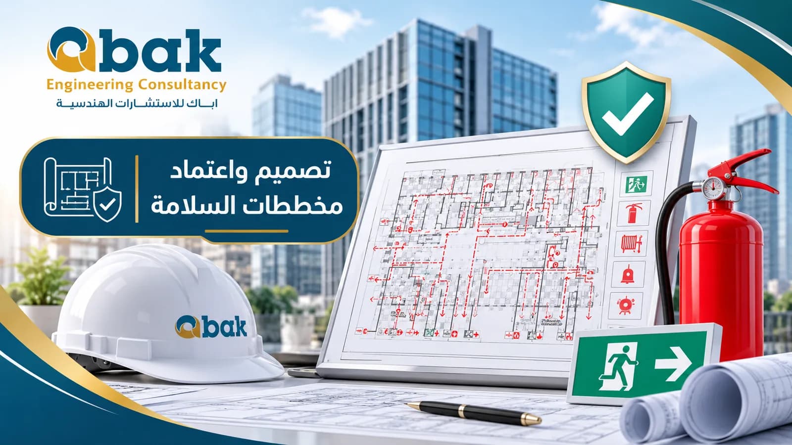
Safety requirements for a tower or multi-story building are different from those of a small facility. Evacuation is not limited to horizontal movement, travel distances to exits are usually longer, the number of occupants is greater, and safety systems must operate together across multiple floors. Therefore, simply placing fire extinguishers or exit signs is not sufficient. The project requires an integrated safety drawings package that coordinates architectural, electrical, mechanical, and fire protection systems.
Designing safety drawings for buildings and towers at an early stage helps reduce clashes, redesign, and costly modifications. It also allows the project team to identify the locations of stairs, emergency exits, fire pump rooms, water tanks, fire alarm systems, firefighting systems, and smoke control systems before construction begins. Installing systems without an approved safety plan may lead to relocating pipes and cables, changing doors and escape routes, or receiving comments and rejection during technical review and site inspection.
In this guide, ABAK Engineering Consultancy explains the main components of approved safety drawings for buildings and towers, how they are coordinated in accordance with the Saudi Building Code SBC 801, the role of the engineering consultant, and the common reasons for returning or rejecting Civil Defense drawings.
What Is an Approved Safety Plan for a Building or Tower?
An approved safety plan is a package of engineering drawings that presents the fire prevention and fire protection requirements of a project. The drawings are prepared according to the occupancy classification, building height, floor area, number of stories, and intended use of the building.
The package generally includes architectural life safety drawings, fire alarm drawings, firefighting and sprinkler drawings, emergency lighting and exit signage drawings, smoke control and ventilation drawings, technical details, schedules, specifications, and the necessary calculations.
Approval means that the design has been submitted through the appropriate process, reviewed by the relevant authority or competent office, and accepted as a reference for the project. However, approval does not mean that the systems have already been installed or tested. Installation, testing, commissioning, inspection, and operation are subsequent stages that must be completed in accordance with the approved drawings.
Why Do Towers Require Specialized Safety Design?
Towers and high-rise buildings require careful engineering analysis because of their height, occupant density, long evacuation routes, and reliance on stairs during emergencies. The design may need to address the following considerations:
- Dividing the building into fire- and smoke-resistant compartments to limit the spread of hazards.
- Providing protected stairs and suitable exits for vertical evacuation.
- Studying stairwell pressurization and escape corridor protection to prevent smoke infiltration.
- Determining the locations of fire pump rooms, fire water tanks, and Civil Defense connections.
- Ensuring access for Civil Defense vehicles to the site and the required building facades.
- Coordinating the fire alarm system with elevators, ventilation, and smoke control systems where required.
- Providing sprinkler and firefighting systems that cover all floors and special hazard areas.
- Preparing an evacuation plan that can be implemented by occupants, visitors, and facility management teams.
A safety plan for a low-rise building cannot simply be copied and applied to a tower. Building height, use, occupant load, evacuation strategy, and required fire protection systems can be significantly different.
Components of Safety Drawings for Buildings and Towers
Architectural Life Safety and Evacuation Drawings
Architectural life safety drawings identify the occupancy classification, occupant load, number and width of exits, travel distances, circulation paths, stairs, doors, and fire-resistant compartments. In towers, the drawings should clearly show vertical evacuation routes, protected stairs, refuge or waiting areas where applicable, floor exits, and the corridors leading to those exits.
The drawings should also identify hazardous service rooms, such as electrical rooms, generator rooms, transformer rooms, kitchens, and fuel rooms. They should show how these areas are separated from the rest of the building, in addition to Civil Defense access routes and assembly areas.
Fire Alarm Drawings
Fire alarm drawings define the locations of the fire alarm control panel, detectors, manual call points, audible and visual notification appliances, zoning, cable routes, and backup power sources.
In towers, the alarm system must be coordinated with typical floors, concealed spaces, suspended ceilings, common areas, service rooms, and vertical shafts. Where required, alarm signals should also be coordinated with other systems, including elevators, smoke control, ventilation, access control, and emergency operation sequences.
Sprinkler and Firefighting Drawings
Fire protection drawings show the locations of sprinklers, fire hose cabinets, portable extinguishers, fire pumps, water tanks, valves, external fire department connections, and pipe routes.
Towers commonly require hydraulic calculations to determine flow, pressure, pipe diameters, pump capacity, and water tank capacity. The design should take into account the different risks associated with offices, apartments, hotels, parking areas, restaurants, kitchens, storage rooms, and special hazard spaces.
Smoke Control and Stair Pressurization Drawings
Smoke control is one of the most important parts of safety drawings design for towers. The drawings may include smoke exhaust fans, air ducts, fire-rated dampers, stair pressurization, escape corridor pressurization, control zones, power sources, and the operating sequence during a fire alarm.
These systems must be coordinated with doors, fire compartments, HVAC ductwork, fans, suspended ceilings, and building services. Any coordination issue may reduce system performance or prevent proper installation on site.
Emergency Lighting and Exit Signage Drawings
These drawings identify the locations of emergency lights, exit signs, directional signs, and evacuation movement paths. Their purpose is to keep escape routes visible and usable during a power failure.
In multi-story buildings, emergency lighting should be reviewed in stairs, corridors, exits, common areas, parking areas, assembly points, and other areas required for safe evacuation.
Fire Pump Rooms, Water Tanks, and Special Systems
Architectural and mechanical details should clearly show fire pump rooms, fire water tanks, Civil Defense connections, valves, control devices, access routes, and maintenance clearances.
Towers may also require special fire protection systems for commercial kitchens, electrical rooms, generator rooms, telecommunication rooms, parking areas, or spaces containing flammable or combustible materials. The selected systems must be coordinated with the building use and the applicable requirements.
Coordination Between Architectural, Electrical, and Mechanical Drawings
A safety plan cannot be successful if each discipline is prepared independently. The architect defines exits, stairs, fire compartments, doors, and evacuation routes. The electrical engineer defines the fire alarm system, emergency lighting, wiring, and power supplies. The mechanical engineer defines sprinklers, piping, pumps, water tanks, ventilation, and smoke control systems.
The following are examples of coordination issues that should be identified before approval:
| Discipline | What It Shows | Common Tower Coordination Issues |
|---|---|---|
| Architectural | Exits, stairs, doors, fire compartments, and evacuation routes | Changing the floor layout, reducing corridor width, or obstructing a stair door |
| Electrical | Fire alarm devices, detectors, cables, emergency lighting, and power supplies | Conflicts between detectors, lighting fixtures, ceilings, and building services |
| Mechanical | Sprinklers, pipes, pumps, tanks, ventilation, and smoke control | Conflicts between pipes, air ducts, beams, ceilings, and other services |
Coordination is especially important in typical repeated floors, parking areas, lobbies, kitchens, service rooms, loading areas, and plant rooms because these areas contain several systems and different levels of risk.
Stages of Designing and Approving Safety Drawings
- Collecting project information: Architectural, structural, electrical, and mechanical drawings, building height, number of floors, areas, use, occupancy, and site information.
- Classifying the building: Determining the occupancy classification, hazard level, applicable SBC 801 requirements, and the relevant authority requirements.
- Planning evacuation: Determining the number of exits and stairs, their widths, travel distances, fire compartments, and assembly areas.
- Selecting the systems: Defining fire alarm, sprinkler, firefighting, fire pump, water tank, smoke control, and emergency lighting systems.
- Preparing calculations: Completing hydraulic calculations, pump and tank capacity calculations, detector and sprinkler coverage, and smoke control or ventilation calculations where required.
- Preparing the drawings package: Producing plans, sections, details, schedules, specifications, and the general site plan.
- Reviewing and coordinating: Checking clashes and ensuring that drawings and project data match the design and actual conditions.
- Submission and approval: Submitting the complete package through the approved process, responding to comments, and updating drawing revisions.
- Installation and testing: Installing the systems according to the approved drawings, testing them, and documenting the results before inspection or operation.
Requirements for Civil Defense Drawings for Towers
Safety drawings should normally include sufficient information to help reviewers, contractors, and facility management teams understand the building without ambiguity. This information may include:
- Project name, address, drawing number, and revision number.
- Building height, number of floors, uses, and occupant loads.
- General site plan and Civil Defense vehicle access points.
- Floor plans for all levels, typical floors, and parking areas.
- Locations of protected stairs, emergency exits, and evacuation routes.
- Fire-resistant compartments and vertical service shafts.
- Fire pump rooms, water tanks, and Civil Defense connections.
- Fire alarm, sprinkler, firefighting, and smoke control drawings.
- Equipment schedules, symbols, specifications, and calculations.
- Professional signatures, stamps, and consultant information where required.
Common Errors That Delay Tower Drawing Approval
Common reasons for returning safety drawings include failure to clearly show vertical evacuation, insufficient stairs, missing fire and smoke compartments, lack of fire pump or water tank information, and failure to coordinate the alarm system with elevators or ventilation where required.
Other recurring issues include using outdated drawings, inconsistencies between the tower area and the building permit, failure to update typical floors, missing hydraulic calculations, sprinkler layouts that do not account for ceilings or obstructions, and pipe or cable routes that conflict with structural elements and other services.
When Should Safety Drawings Be Updated?
Safety drawings should be reviewed and updated when the use of the tower changes, floor layouts are modified, an additional area or mezzanine is added, the number of occupants changes, stairs or exits are modified, fire alarm, sprinkler, or smoke control systems are changed, fire pump rooms or water tanks are relocated, or construction work does not match the approved drawings.
For existing buildings, the review should begin with a site survey, photographs of the installed systems, field measurements, and a comparison between the approved drawings and the actual construction. Updated as-built drawings or existing-condition drawings can then be prepared before submission for approval when required.
How Can ABAK Engineering Consultancy Help?
ABAK Engineering Consultancy provides safety drawings design services for buildings and towers, including Civil Defense drawings, evacuation plans, fire alarm drawings, firefighting and sprinkler drawings, smoke control drawings, and emergency lighting drawings.
Our work includes coordination between architectural, electrical, and mechanical disciplines. The process begins with studying the project, classifying the building, and identifying the applicable SBC 801 requirements. We then prepare the drawings package, calculations, schedules, and technical details, review potential clashes, submit the drawings through the appropriate process, and follow up on technical comments until approval.
For existing buildings and towers, ABAK can also inspect the current conditions, identify differences between the approved drawings and installed systems, and determine the modifications required before inspection.
Frequently Asked Questions
Are safety drawings for a tower different from those for a low-rise building?
Yes. They differ because of building height, vertical evacuation, occupant density, smoke control systems, stair pressurization, longer travel distances, and Civil Defense access requirements.
Does approval of the safety drawings mean that the tower is ready for operation?
No. Approval relates to the design. The systems must still be installed, tested, commissioned, documented, and inspected before the building can complete the required licensing and operational procedures.
Do towers require smoke control drawings?
They may be required depending on the height, design, occupancy, basement levels, evacuation routes, and applicable regulations. The engineering consultant determines the required scope after studying the project.
Can drawings for an existing building be approved?
Yes. The existing building must be inspected and updated drawings must be prepared to match the actual building and installed systems. Any differences and technical comments should be addressed before submission.
What is the difference between an evacuation plan and safety drawings?
An evacuation plan focuses on escape routes, emergency exits, and assembly points. A complete safety drawings package includes architectural, electrical, mechanical, fire alarm, firefighting, sprinkler, and smoke control systems.
How can I choose an approved fire safety consultant?
Check the consultant’s professional approval and experience in fire prevention and protection, particularly for towers and multi-story buildings. The consultant should also be capable of coordinating disciplines, preparing calculations, and following up on the approval process.
Official References
- Saudi Civil Defense — Guide for Submitting a Compliance Report for Fire Prevention and Protection Requirements
- Saudi Building Code — SBC 801
- SBC 801 Table of Contents — 2024 Edition: View the Table of Contents
- Saudi Civil Defense — Approved Engineering Consultancy and Technical Services Offices
- Salamah Portal